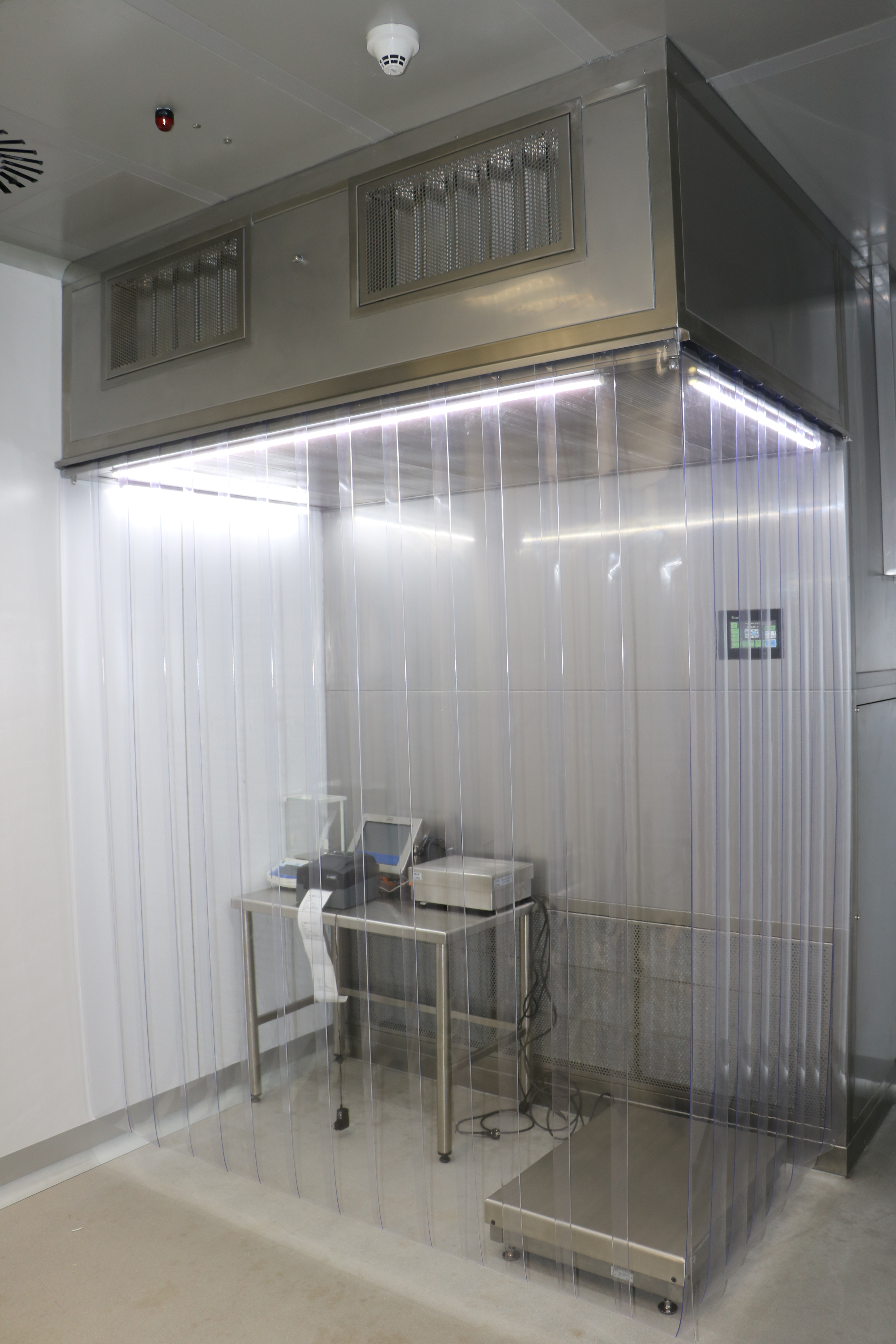
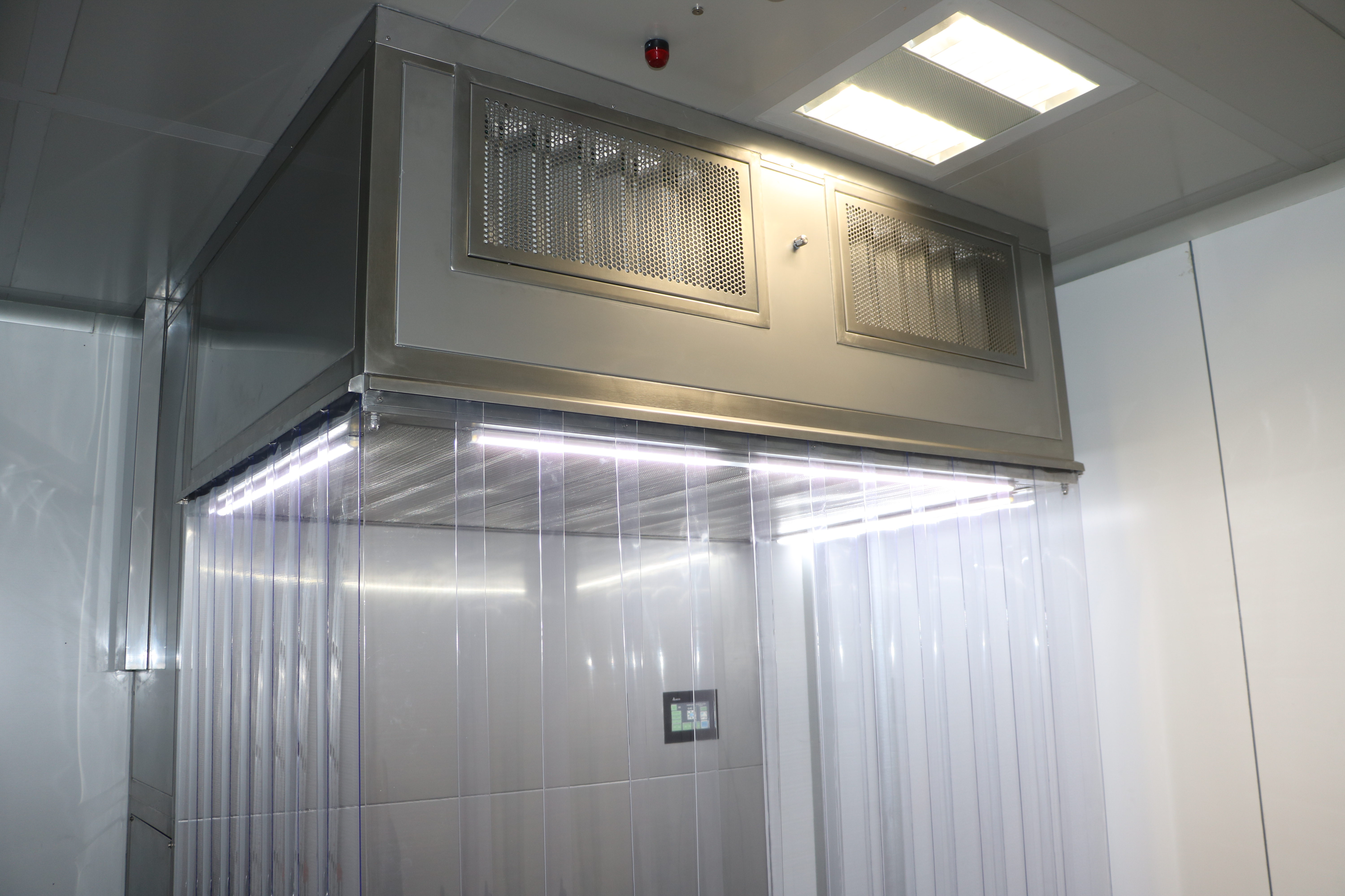
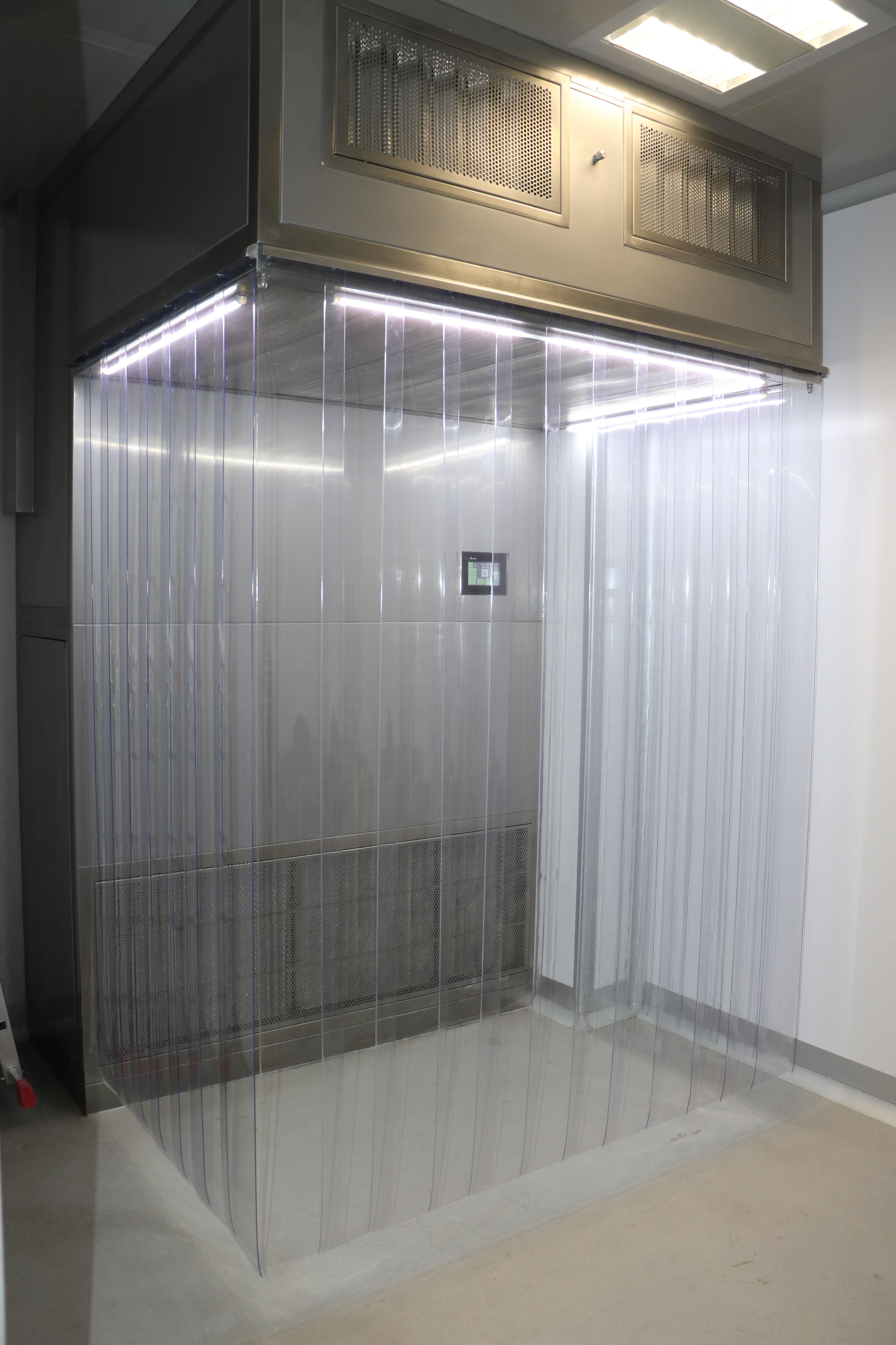
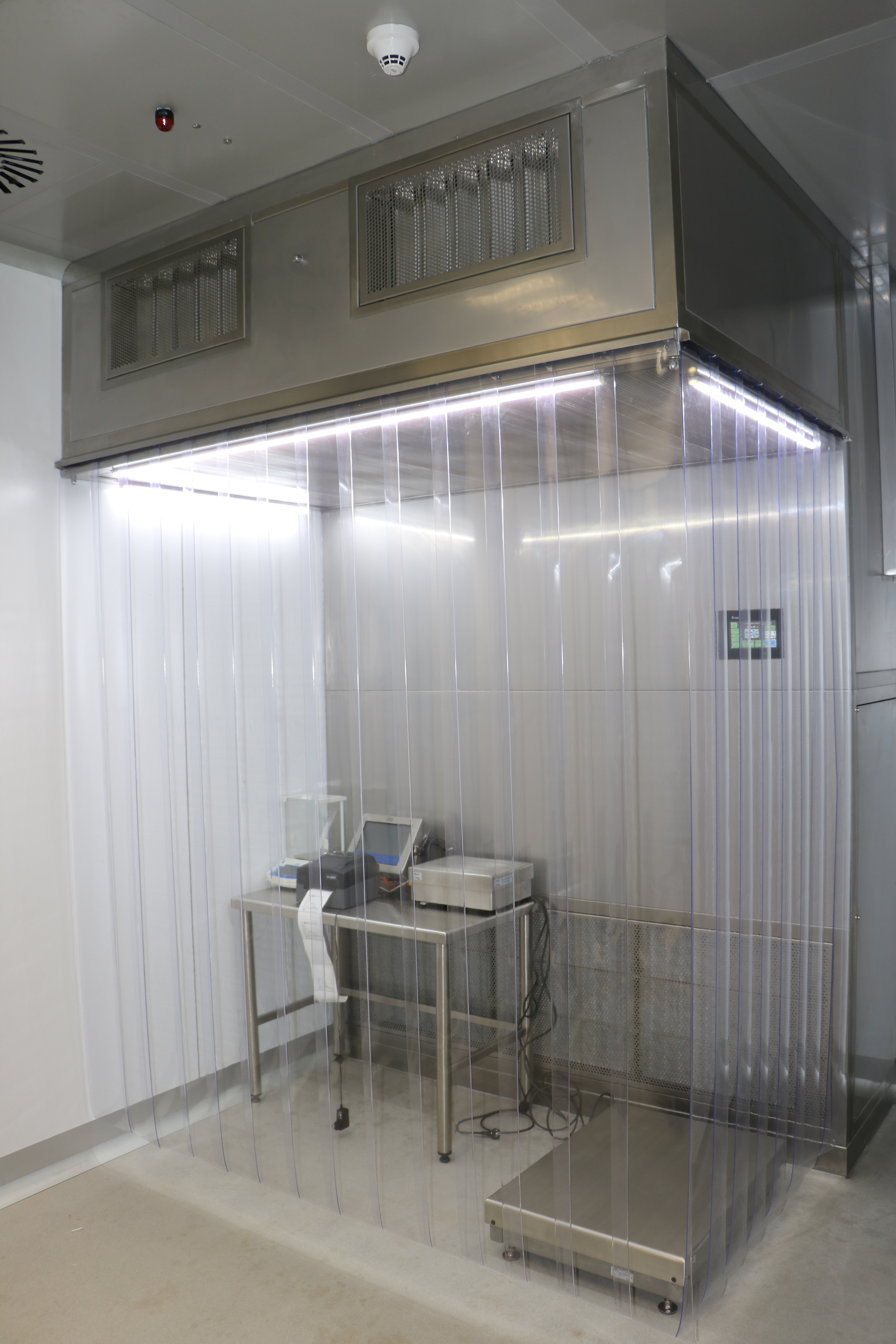
These laminar flow cabins consist of prefilters, fans, HEPA filters (H13/H14), lighting fixtures, electric and automatic control systems, PVC curtains, wheels or parts for hanging from ceiling. Also, day/night set back energy savings, alarm feature for motor failure and emergency shut down available on request with AC control systems.
Introduction
• LF provides the highest levels of operator protection from potentially harmful airborne contaminants generated during manual powder handling operations such as weighing, sampling, charging and dispensing.
• Unit provides product protection (Class ISO 5) from surrounding area contamination by creating a clean processing zone minimizing cross contamination risk from other products/processes.
• Class ISO 5 according to ISO EN 14644-1 (Class l 00 according to Fed. Std. 209 E)
• A negative pressure inside the unit prevents the escape of fine powders from the work area towards the external environment.
• LF cabins consist of two stage pre-filters, fans, HEPA filters (H 13/H 14), lighting fixtures, electric and automatic control systems, PVC curtains, front legs or parts for hanging from ceiling.
• Flexible PVC strip curtains and/or rigid walls increase the protection by separating the working area and external environment between each other.
• Airflow filtered by a two stage of pre-filters. Also partially exhausted to create inside negative pressure after HEPA filtration.
• Airflow recycled through the HEPA filters to generate the laminar flow.
Specifications
• Laminar airflow velocity of 0.45m/s ± 20% measured 150 mm from HEPA filter or diffuser face
• Used for production, weighing, sampling and packaging
• Custom filtration systems to suit each application including HEPA filter
• Leakage test with test aerosol according to ISO 14644-3 for HEPA filters
• Optional cooling coil systems for temperature regulations
• In various dimensions and safe working zones
• Test aerosol inlet nozzle
• Fan FlowGrid to reduce noise level
• Safe change filter configurations and internally or externally change available
• cGMP modular design with minimized joints and seams
• Airflow configurations allowing use for powder or solvent applications
• Ceiling or side wall mounted LED lighting, UV lighting available
• Available in a variety of construction materials, including 304/316 stainless steel
LF Unit;
• protects the product and the operator
• protects the inner and external environment
• reduces operating and maintanence costs
• saves energy with the advanced equipments
Application Area
LF units are used in the pharmaceutical, fine chemical, cosmetic and food industries for operations such as sampling, weighing, and filling which generate airborne particles; when processes involve hazardous, toxic or hormonal materials. Operators, adjoining areas require protection from exposure to aerosols of the process materials.
Operation principle
- The LF Unit operates on a recirculatory push-pull airtlow principle providing containment by air movement.
- 85-90% of overall air quantity evenly goes through HEPA filter into the entire of the working space pushing any respirable dust clouds generated during open powder processing, removing and capturing airborne particles and away from the operator’s breathing zone.
- The contaminated air passes through the perforated return grilles and two stages prefilter before returning through the unit ceiling plenum.
- The rest of air, 10-15% is exhausted through HEPA filter into surrounding environment to create the working space under negative pressure, minimizing airborne contamination breakout. This air quantity is being made up by drawing air from external environment.
Airflow Control
- The airflow control is made with an automatic regulation of the fan speed obtained by airflow sensors that control the value and allow to keep the airflow to its nominal value.
- There are differential pressure gauges for pre filters and main filter. The filters should be changed when they reach the recommended final pressure drop for protecting system and saving energy.
Advantages of System
- The LF design has no impact on the existing HV AC or room pressures
- Low noise levels due to advanced fan and isolation inside the ceiling plenum
- Capability to integrate additional process equipment
- Unrestricted operator access to the target operation
- User friendly and ready to easy use
- Reduced installation and commissioning times
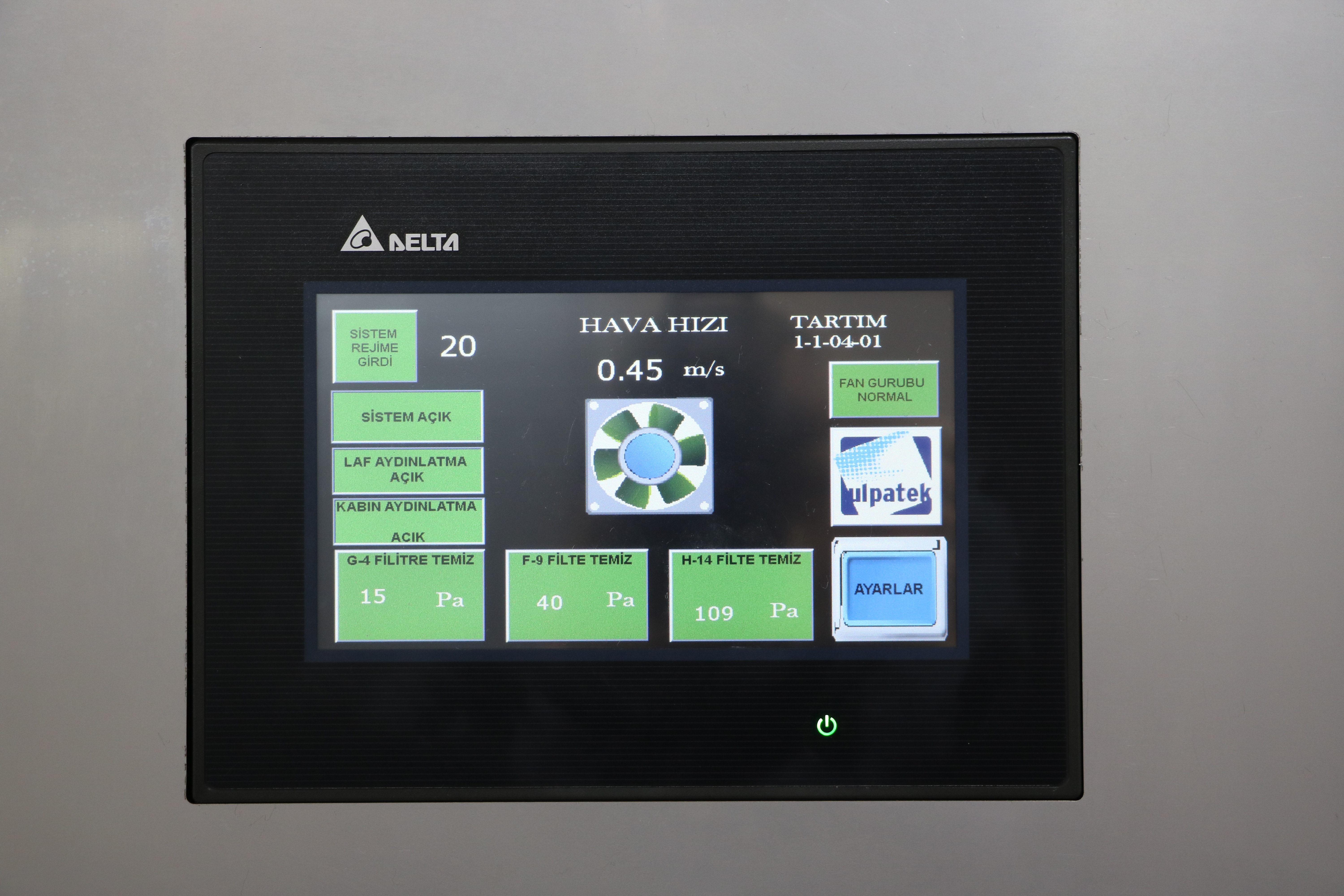
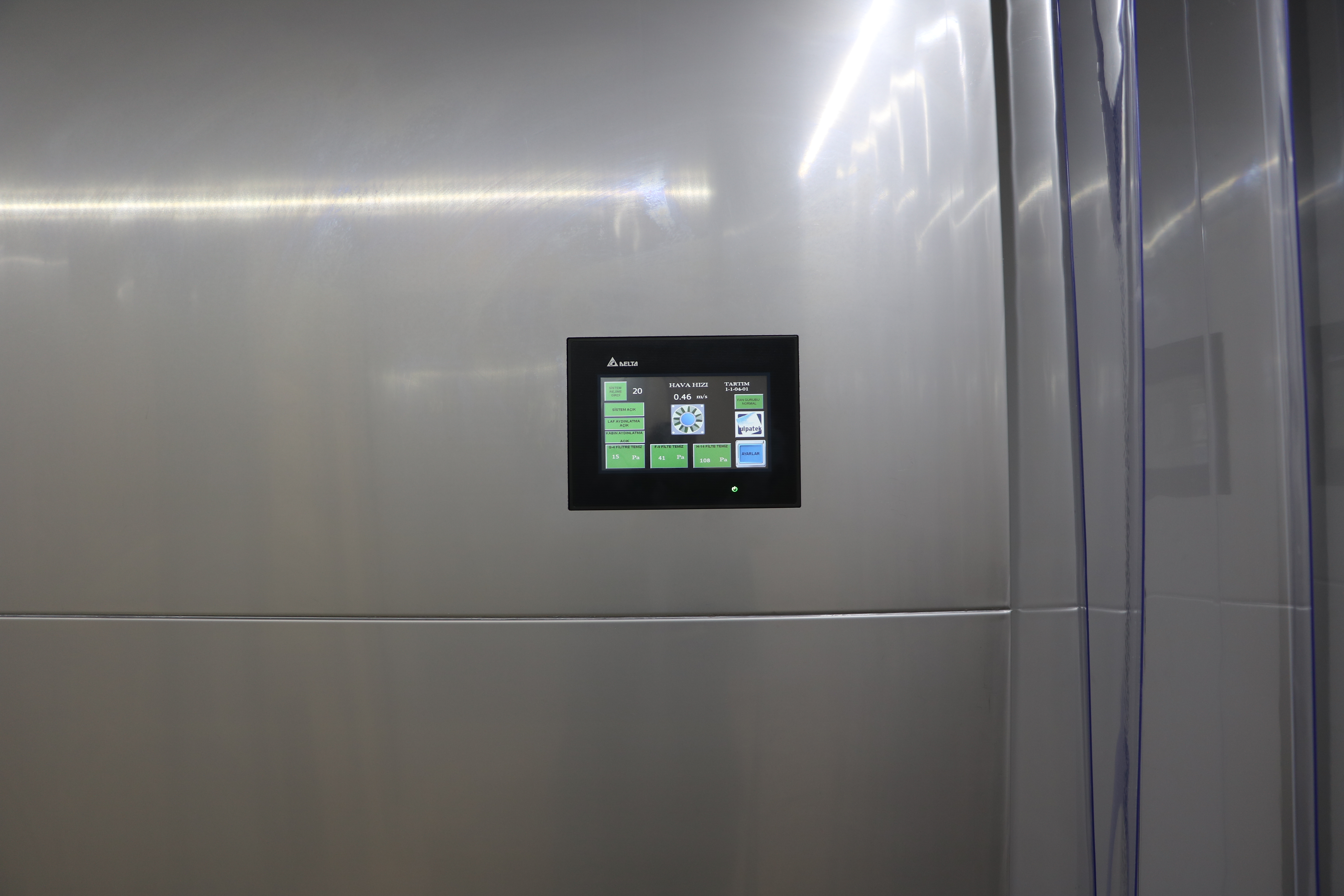
The control panel and the electrical cabinet are placed on the vertical backside wall or outside of the unit that is made of AISI 304 stainless steel (IP55). The system starts by turning the main switch on position “I”.
On the panels there are the following components:
• Display for air velocity (m/s)
• Fan START/STOP push button
• Lighting ON/OFF push button
• Differential Pressure Gauges
• Visual alarm (Acoustic optional)
• Emergency Stop
• Remote START/STOP contacts for BMS connection
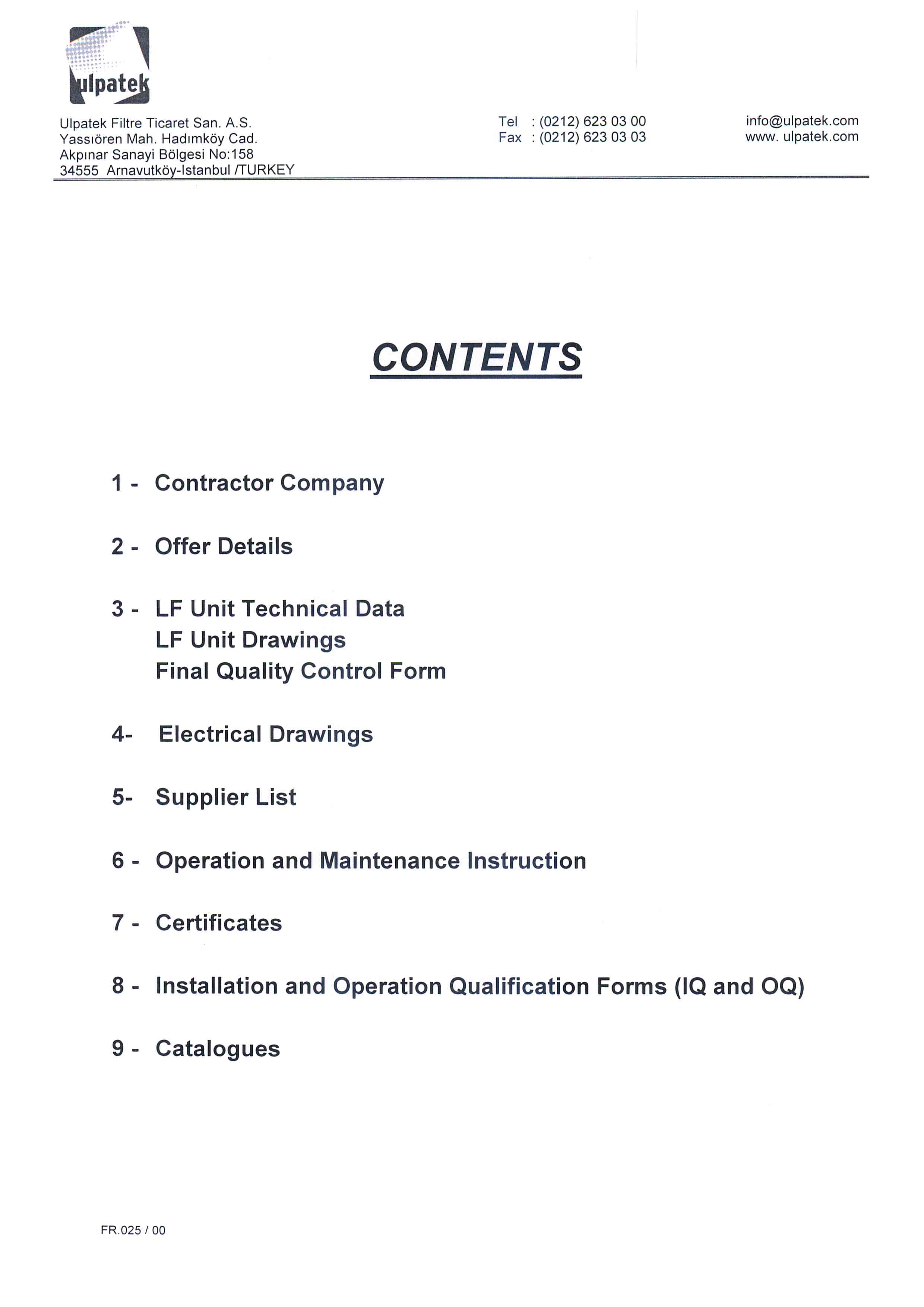
Documentation
The following documentation will be supplied:
| Offer Details | Supplier List |
| LF Unit Technical Data | Operation and Maintenance Manual |
| LF Unit Technical Drawings | Certificates |
| Final Quality Control Form | Installation and Operation Qualification Forms (IQ and OQ) |
| Electrical Drawings | Catalogues |

